We used one Elegoo Uno R3, one GY-521 module and 4 F-M wires, then we finished the following connection:


We used one Elegoo Uno R3, one GY-521 module and 4 F-M wires, then we finished the following connection:
The materials used: 1 elegoo UNO R3, max7219 matrix module and 5 f-m dupont wires.


The materials we used: 1 elegoo Uno R3, 1 membrane switch module and 8 m-m wires.


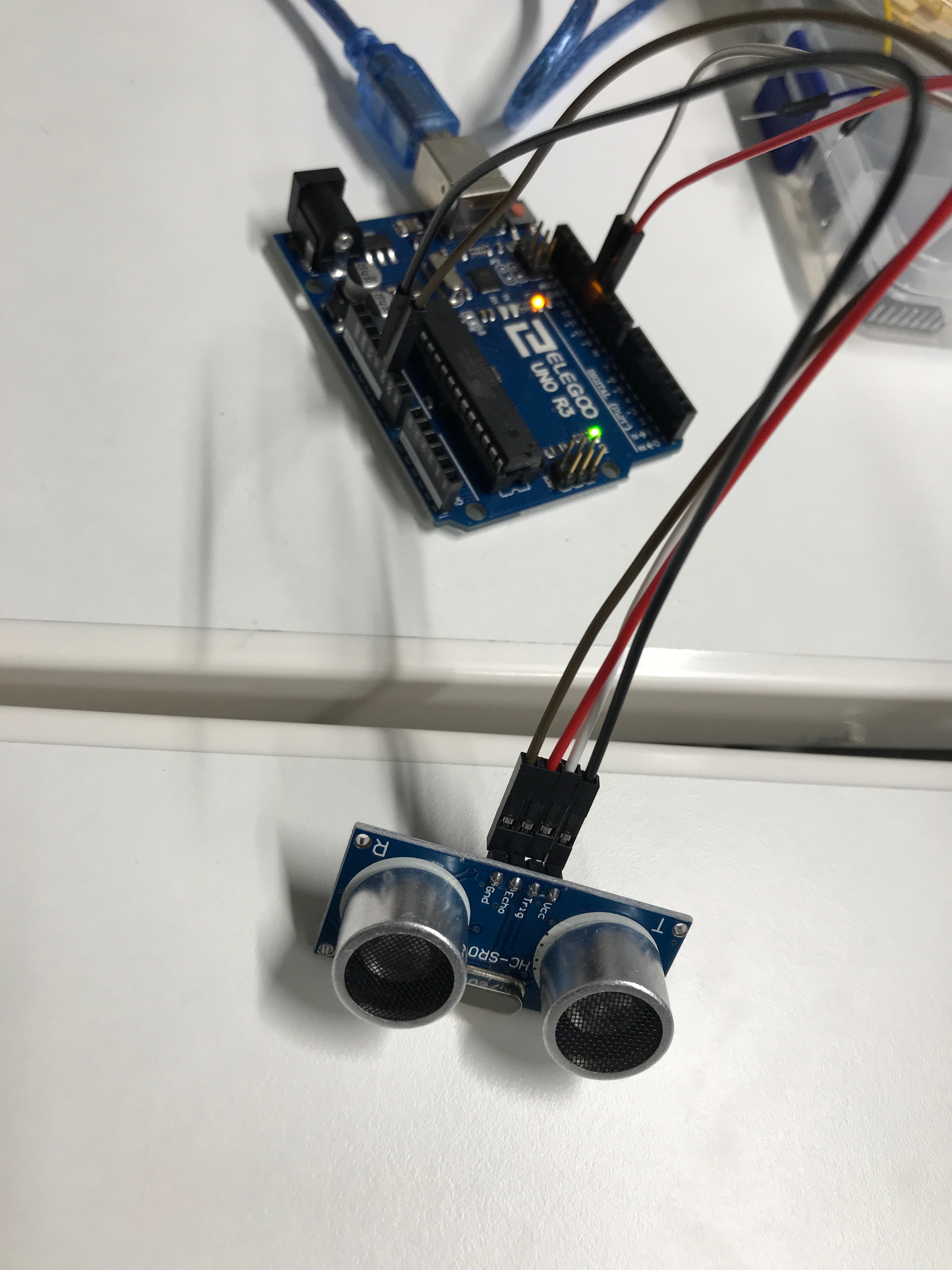
The materials we used: 1 uno R3, ultrasonic sensor module and 4 f-m wires.


The materials we used: 1 Uno R3, servo motor and 3 m – m wires.


Components used: Elego Uno R3, Tilt ball switch and 2 F-M Dupont wires.
The presets on the code allow the tilt ball switch to turn the led on when pointing the tilt ball switch upwards.


We used: elego uno R3, female to male dupont wires and one passive buzzer. The original codes the eight different sounds, each sound lasting 0.5 seconds: from Alto Do (523Hz), Re (587Hz), Mi (659Hz), Fa(698Hz), So(784HZ), La(880Hz), Si(988Hz) to Treble Do (1047Hz).

As a test, we change the frequency and duration of the notes.

We used: Elegoo Uno Controller, one Active buzzer and 2 F-M wires.

We tried to change the frequency from the original 100 and 120 to:

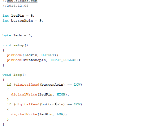
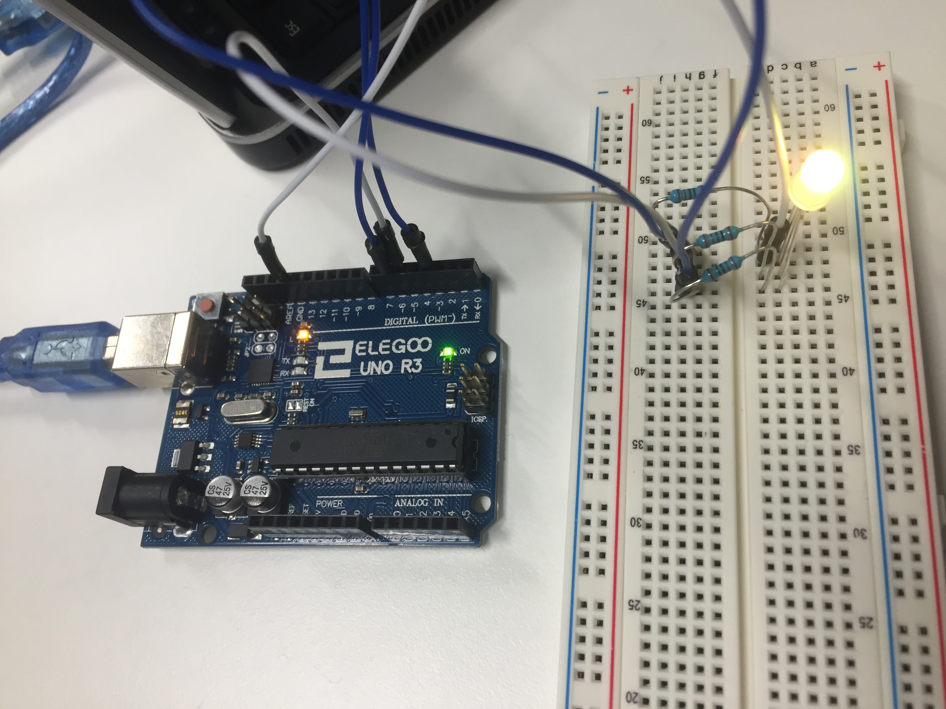
On this lab we used : Elegoo UNO Controller, 830 Tie-points Breadboard, 5mm red LED, 220 ohm resistor, 2 push switches and 7 M-M wires.
For the lab we got the Arduino-made code ready and only had to connect the components correctly to the controller and breadboard. By doing so we were able to switch the LED light on and off by using the two switches.

After the initial work, we changed the code a bit, so that the led would light and turn off by pressing only one switch button.
On this lab we connected the RGB LED to the breadboard with three 220 ohm resistors, we also used four MxM jumper wires to connect them all to Elegoo Uno controller board.
We changed the delay of the fading time of the colours of the LED from the original 10 milliseconds first to 15 milliseconds and last to 5 milliseconds and noticed the change after those.
We changed the brightness of the colours from:

To:

And thus noticed the change in the brightness of the colours in the LED.
